The specification we are describing here is for a product I work on where we would like system administrators to send requests to users in the form of messages. For this example, we are only looking at the state transition diagram for the messages.
What does Spec Explorer Give Me?
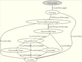
The following diagram and tests were auto-generated based on the model specified for Spec Explorer.
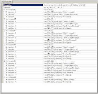
The following diagram and tests were auto-generated based on the model specified for Spec Explorer.
For now, note that the tests below are labeled 'test segment 0', 'test segment 1' etc. and that the transitions From S0 to S3 represent 'State 0' and 'State 3' respectively. The diagram correctly describes these states and I'll describe how to understand how 'State 0' is associated with the name 'NotCreated' later in this blog entry.
While the diagram isn't the easiest to follow, some deference should be given since it was generated by the model created in the spec. However, you should be able to see that the message starts in a 'Not Created' state, then is moved to 'Pending' etc. until it is ultimately in the 'Deleted' state.
The transitions are the actions taken to move from one state to another such as 'UserViewMessage' and 'CreateMessage'.
The test suite shows how to move through each path of this state diagram. In this particular case, we are able to go through all paths because we don't have any loops (such as you would get if you could take a 'RejectedByClient' message and move it back to 'Pending').
If we had such a model, the test suites would be selected using strategies built into Spec Explorer and could be used as a basis for testing.
We can also use Spec Explorer to ensure that our models were complete and accurate before we sent our Specs for review.
Who is Spec Explorer for?
Anyone that writes specs, interprets specs or implements specs can make use of this.
Business Analysts - This can auto-generate use cases and diagrams as well as validate that the model you intend on having implemented is complete and accurate.
Quality Assurance - This can be used to build more extensive models along with more detailed data tracking to generate test cases.
Developers - This can be used to validate technical designs and auto-generate unit tests including basic validation of those tests.
Depending on your desire to dig into the capabilities, you will get more or less from this tool.
How do I get started?
You can get it from Spec Explorer Site at Microsoft Research as well and copy the spec sample below.
Once you have installed Spec Explorer and launch it, create a new project.
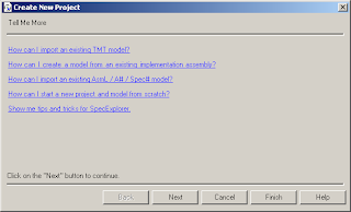
click 'Next'
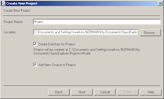
Select the 'Create Directory for Project' checkbox and then Next.
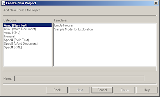
Select the "AsmL (Plain Text)" Category and "Empty Program" Template and click the "Finish" button. One feature that should be mentioned here is that we can embed the markup language into the Word documents used for specs and it will work the same. Spec Explorer will embed MS Word into the file edit window and you can modify the spec as you would normally do.
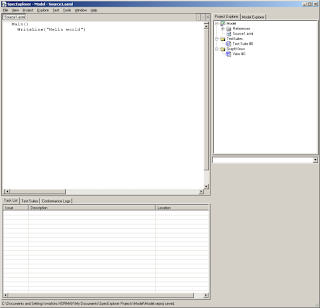
Replace the default text with the following:
enum MESSAGE_STATUSES NotCreated Pending ReceivedByCaptureEngine ReceivedByClient ViewedByClient Completed RejectedByClient Deleted var status as MESSAGE_STATUSES = NotCreated [Action] CreateMessage () require status = NotCreated status := Pending [Action] CERequestMessage () require status = Pending status := ReceivedByCaptureEngine [Action] ClientRequestMessage () require status = ReceivedByCaptureEngine status := ReceivedByClient [Action] UserViewMessage () require status = ReceivedByClient status := ViewedByClient [Action] UserReject () require status = ViewedByClient status := RejectedByClient [Action] UserComplete () require status = ViewedByClient status := Completed [Action] UserDelete () require ((status<> NotCreated) and (status <> Deleted)) status := Deleted Main () |
There are 3 main parts to this spec. Variables and Constants, Actions and the 'Main()' statement.
In the Variables and Constants section for this example, we define the Message Status options and define a variable to keep track of the specific state for a given message.
In the Actions section, we describe each action to the message.
The 'Main()' statement is a necessary part for Spec Explorer to do it's anlaysis. More complex usage of the tool will use this, but not this example.
To generate the graph, we need to do a couple things. First, we'll 'build' a reference implementation of the specification. To do this, click 'Project' -> 'Build'. You'll see messages in the 'Output' tab. Note that in the output, you'll see a hint for each action described.
Next, we'll need to run this reference implementation to generate the diagram. To do this, click 'Execute' -> 'Run'.
You'll get the 'Select Execution Goal' dialog.
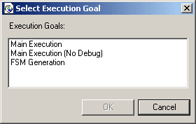
Select 'FSM Generation' then 'OK'. (FSM = Finite State Machine). Remember the S0 and S1 references from the tests generated earlier? Here is how they are seen by default. In order to make the diagram easier to read, we need to associate each state with some value, in this example, we'll associate it with the variable 'status'.
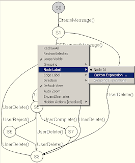
Right-click on the diagram and select 'Node Label' then 'Custom Expression'.

Now, we have the diagram we are looking for. Next, to generate the tests. Simply click 'Test' -> 'Generate Test Suites' and you get the list of tests listed above.
What are some juicy details that can't be covered here?
Using Word Documents with the AsmL Styles is a simple way to ensure that the model is tied to it's diagram and other analysis. You can publish the word document to a document repository and still be able to pull it back into Spec Explorer for future analysis.
There are several markup languages you can use to generate these models, AsmL language and Spec#.
There are other tools to use as well to build and evaluate these models, NModel , dia2fsm and others.
This is not a deep dive into this area, but I'm sure there will be cases where this is helpful.
No comments:
Post a Comment